Page 91 - EEC_HeavyDuty
P. 91
Hardware
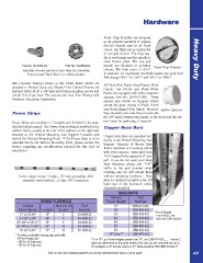
Flush Drop Handles are designed Heavy Duty
as an optional assembly to replace
the Lift Handle used on all Flush
Doors. The flush cup is constructed
of wrought bronze. The drop han-
dle is cast bronze and the spindle is
steel, bronze plate. The cup and
Part No. 80-0304-03 Part No. 80-0604-03 handle are finished in polished Flush Drop Handles
chrome. The flush cup is 2 13/16”
Machine Screws and Hex Keps Nuts for attaching
Pontoon and Flush Bases to cabinet frames. in diameter. To incorporate the flush handle into your door
P/N change “091-” to “097-” and “092-” to “098-”.
The recessed Pontoon Bases or the Flush Bases which are All Flush Side Panels, Rear Panels, Front
attached to Vertical Rack and Sloped Front Cabinet Frames are Panels, Top Panels and Flush Filler
fastened with 1/4-20 x 3/4” Hex Head Sems machine screws and Panels are equipped with white neoprene
1/4-20 Hex Keps nuts. The screws and nuts Zinc Plating with spacers, Part No. 260-018-000. These
Trivalent Chromium Passivation. spacers also double as bumpers which
assure the quiet closing of Flush Doors
Power Strips and Flush Hinged Side Panels. Because Rubber Spacers
they are easily removed, they can provide
the 1/8” space between the panels, or the doors and the cab-
Power Strips are available in 5 lengths and finished in the stan- inet frame for gasketing, if required.
dard tan baked enamel. The Power Strip is shipped installed in the
cabinet frame, usually at the rear of the cabinet, on the right side Copper Buss Bars
attached to the Vertical Mounting Rail Support Channels and
behind the Vertical Mounting Rails. If the Power Strip is to be Copper Buss Bars are mounted ver-
installed before the Vertical Mounting Rails, please contact the tically to the Vertical Mounting Rail
factory regarding any modifications required for this type of Support Channels of Heavy Duty
installation. Racks insulated at mounting points
with nylon spacers. Buss Bars have
10-32 tapped holes spaced at 6” cen-
ters. If you do not want your Buss
Bars insulated, please add “-CG”
3 wire, single circuit, 15 amp., 125 volt, grounding, ASA suffix to the part number when
standard, wired with No. 12 Type TW Conductors ordering and we will mount them
without insulating hardware. Buss
Bars are shipped mounted in the left
hand rear of the enclosure unless
otherwise specified.
BUSS BARS
WIRED PLUGMOLD Vertical Part
Panel Height Number
Vertical Number of Part 21” CBB-021-032
Number 28” CBB-028-032
Panel Space Length Outlets 35” CBB-035-032 * For all Sloped
03-0306-32 42” CBB-042-032 Front Racks, use
21” to 29 3/4” 18” 3 03-0506-32 49” CBB-049-032 Buss Bar CBB-136-032
31 1/2” to 35” 30” 5 03-0606-32 56” CBB-056-032
36” 3/4” to 59 1/2” 36” 6 03-1006-32 63” CBB-063-032
61 1/4” to 71 3/4” 60” 10 03-1206-32 70” & Up ** CBB-070-032
73 1/2” to 84” 72” 12
* To order a cord with 3-prong plug, add suffix ** For 70” Lg in Panel Heights greater than 70”, use CBB-070-032-_ _ The last 2
-6P for 6’ long cord digits are determined by the panel height of the rack you are using the bus bar in.
-10P for 10’ long cord For example, a 70” bus bar used in a 77” frame would be P/N CBB-070-032-77
-15P for 15’ long cord
Visit our web site at www.equiptoelec.com for the latest technical data or a price quote A91